


2.24.21
LAB 5 - BUILD A MUSICAL INSTRUMENT
Assignment:
This lab explores analog output through frequency modulation. You will practice how to connect analog sensors to your Arduino, and connect this input to sound through a piezo buzzer.
Objectives:
-
Continue practicing reading analog sensor values with analogRead(), the serial monitor to debug, and the map() function to bring it into a useful range for your application
-
Use frequency modulation with the tone() command to generate sounds
-
Build a custom musical instrument
Deliverables:
-
A step-by-step explanation of your process. Think of your blog as an Instructable. If a random stranger on the web came across your blog, how easily would they be able to follow along? (That's the main thing we keep in mind while grading).
-
Clear and informative photos and videos of each working circuit with a written explanation of the circuit does. Post the videos on YouTube or Vimeo and embed them in your post.
-
An obvious link or embed of your Arduino code using Github Gist (Links to an external site.)Links to an external site. (screenshots are not acceptable).
-
A schematic drawing of each circuit (you must draw the schematic yourself, do not use the same image from the project guide).
-
Detailed photos and video of your instrument
-
Post a video of your instrument on the course Discord, in the channel #lab-5-instrument-videos. Copy the message link and add it to your documentation.
Part 1 - Tone Output
For this part, I coded the buzzer in Arduino using tone() to output a sound of 1000 Hz for half of a second (500 milliseconds) then pause for one second before playing tone again.

Schematic Diagram:

Step 1: Gather Materials
-
Breadboard
-
Arduino Uno
-
USB Cable
-
Speaker: Passive Piezo Buzzer
-
Black jumper wire
-
Red jumper wire
Step 2: Connect the Buzzer
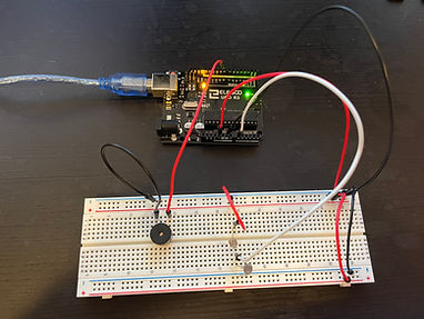
I used one red and one black wire for the positive and negative connections. The buzzer is labeled on the top with a +, so I used the red wire to connect it to pin 8. The black wire is going from the negative side of the buzzer to GND on the Arduino Uno.
Then I plugged in my Aurdiono and uploaded my code!
Part 2 - Analog Sensor Input
In part 2, I am going to be adding two light-dependent resistors (LDRs) to my circuit from above.
Step 1: Gather Additional Materials
-
Black wires (x3)
-
Red wires (x2)
-
White wire
-
Light-dependent resistors (x2)
.jpeg)
Step 2: Bring Power to Breadboard
Because I am now using LDRs to affect the sound output, I need to bring power across my breadboard. To do this, I'm using four new wires (two red and two black). The long red wire is going from the 5V pin on the Arduino to the positive terminal, and the shorter red wire connects the positive terminals. The long black wire is going from the GND pin on the Arduino to the negative terminal, and the shorter black wire connects the negative terminals.
I also connected the negative leg of the buzzer to the negative terminal rather than the GND terminal on the Arduino as seen to the left.
.jpeg)
Step 3: Add LDRs
Next, I added two LDRs which will act as inputs to my breadboard to make a voltage divider circuit.
I connected a white jumper wire from the pin A0 to the junction point between the two LDRs. The terminal end of one photoresistor was connected to 5V (power) with another red wire, and the terminal of the other photoresistor was connected to GND to complete this circuit.
Step 4: Update the Code
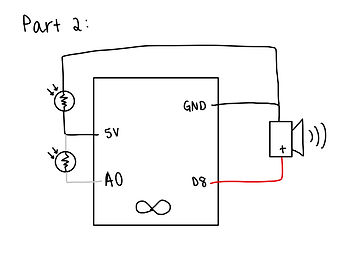
Finally, I updated my code so the LDRs would interact with the buzzer. When the bottom LDR is covered, the frequency increases, and when the top LDR is covered, the frequency decreases.
Schematic Diagram:
Part 3 - Make a Push-button Piano
This part will explore controlling the buzzer with buttons.
Step 1: Gather Additional Materials
-
Blue jumper wires (x2)
-
White jumper wires (x2)
-
Buttons (x2)
.jpeg)
Step 2: Connect Buttons to the Circuit
This part required me to replace the two LDRs with buttons. I used the blue wires to connect the left button and the white wires to connect the right button.
For the left button, the long wire is going from the right side to pin 7. The short wire is going from the left side of the button to the negative terminal.
For the right button, the long wire is going from the right side to pin 4. The short wire is going from the left side of the button to the negative terminal.
Step 3: Code the Buttons
Finally, I coded my buttons as inputs and set them as pull-up resistors under void setup() by using the internal resistors in the buttons. I made it so when the left button is pressed it emits note C6 which is high pitched, and when the right button is pressed, it emits note C3 which has a low pitch.
Schematic Diagram:

Part 4 - DIY Instrument
In Part 4, I will be making a custom piano by implementing the concepts in the previous parts.
Resources:

Step 1: Gather Materials:
-
Breadboard
-
Arduino Uno
-
Battery and connecting wires
-
USB Cable
-
Speaker: Passive Piezo Buzzer (black bottom)
-
1M ohm resistors (x5)
-
Jumper wires (x18):
-
Black (x4)
-
Red (x4)
-
White (x3)
-
Blue (x2)
-
Green (x2)
-
Yellow x2)
-
Orange (x2)

Step 2: Repeat Step 2 from Part 1
We are still using a buzzer, so I repeated step 2 from Part 1 and used two red, three black, and one white wire to bring power to the breadboard. However, instead of going to pin 8, I connected my buzzer to output pin A0.

Step 3: Start Wiring
This is explained more in my Arduino code, but I am using two green wires to represent my send pin for the capacitive sensor. This is connected to pin 2.
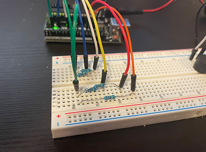
Then, I used my resistors and placed them as shown. The left end of every resistor is in series with the green wires. I had to cut some of them so they were different lengths. You'll see in step 5 why I have done this.
Step 4: Create connections with the rest of the pins
I used five different colored wires (blue, white, yellow, red, and orange) because I wanted five notes for my piano (C - G).
As you can see, one end of the wire is put in line with the right end of the resistor and the other end is going to a pin on the Arduino. I used ins 4, 7, 8, 12, and 13)

Step 5: Add free wires and code
Finally, I added five more wires in the same colors. These wires are coded to be our sensors, so when you touch the free-floating end, it will output the corresponding note. I have marked the added wires with a white dot.
After this, I connected the USB and coded the Arduino so the blue wire plays note C, white plays D, yellow plays E, red plays F, and orange plays G when the free end of the wire is touched. I then uploaded this to the Arduino.
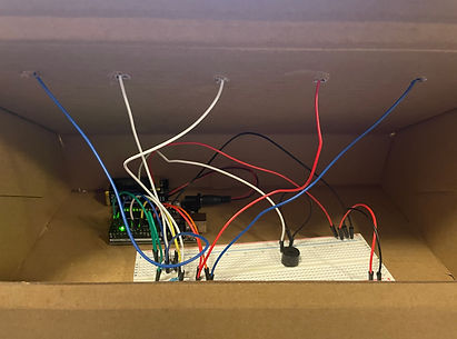
Close-up of all the connections:

Completed circuit from above with battery:
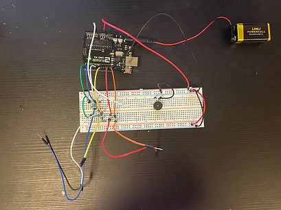.jpeg)
.jpeg)
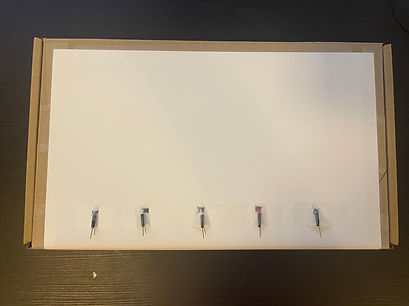
Step 6: Make the enclosure
I used an old box and placed a piece of paper over the top. Then I placed my circuit inside and made five holes for each of the five wires.
Note: I replaced the orange and yellow wires with longer ones so they will reach through the top.
I made little squares of foil and placed them on top to cover the ends of the wires and act as buttons.
I decorated it by adding the notes to "Mary Had a Little Lamb" and labeling each note!
.jpeg)
.jpeg)
Schematic diagram:

Video of my working piano: