


2.10.21
LAB 3 - ARDUINO AND DIGITAL I/O
Assignment:
In this lab, you will learn about the Arduino prototyping environment and explore how to use the digital inputs and outputs of your microcontroller. You will integrate these into a project by building a custom switch and enclosure.
Objectives:
-
Get set up with and understand the Arduino environment
-
Build a circuit with a digital input (switch) and two digital outputs (LEDs)
-
Program the Arduino to power the LEDs based on the switch state
-
Prototype a custom switch and enclosure
Deliverables:
Part 1: A digital I/O circuit, where (at least two) input switches will turn (at least two) output LEDs on and off.
-
A schematic, photograph, and description of your circuit
-
The code of your Arduino program is embedded or posted via a very obvious link to Github Gist (Links to an external site.)
-
A video of the digital I/O circuit working
Part 2: A DIY switch integrated into a digital I/O circuit
-
Photos and description of the materials you use for your switch (include any failed experiments as well)
-
The code of your Arduino program is embedded or posted via a very obvious link to Github Gist (Links to an external site.)
-
A schematic and a photo of your circuit
-
A video that explains how your switch works
Part 3: Creative Enclosure
-
A photo of your final enclosure open and closed
-
A video that demonstrates the final project with the enclosure working
Part 1 Documentation: Digital I/O Switches
For this circuit, I went off of the one we did in lab, but replaced the white LED with a green one because I wanted to mimic a stoplight. I changed the names of the buttons in Arduino to buttonLeft and buttonRight. When buttonRight is pressed, the LED's will flash and when buttonLeft is pressed, all three LEDs light up. A link to my code can be found
Photo of my circuit:

Close up of circuit:


Schematic diagram:
Video of working circuit:
Part 2 Documentation: A DIY switch integrated into a digital I/O circuit
For this circuit, I kept it the same as above but switched out the red and yellow LEDs for green ones. I changed the variables in the beginning to all reference the green LEDs. I also swapped the code beneath buttonRight and buttonLeft, so when the circuit is closed, the lights will flash instead of just be on.
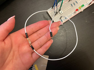
For my switch, I replaced buttonLeft with three wires. I used a regular jumper wire and connected it to a female to male Dupont wire and secured it with copper tape. Then, I created a basket with tin foil and secured it to the connection with more copper tape. Finally, I connected another jumper wire to where the top left leg of buttonLeft was. I covered the free end of this jumper wire in a ball of foil so when you make a basket, the circuit is closed and reads LOW causing the green lights to flash as if you won! A link to my code can be found
Replaced buttonLeft with wires and connected them with copper tape:
.jpeg)
.jpeg)
Tin foil asket attached to connected wires:
New circuit:
.jpeg)

Schematic diagram (same as above, but changed names of switch and LEDs):

Video of working switch:
Part 3 Documentation: Creative Enclosure
For my enclosure, I used a cardboard box that was just long enough to fit the breadboard. I covered it in duct tape and then cut a hole in the side for the lights to show through. I covered that with tape so the box was enclosed again. Then, I poked three holes in the top for the wires that were attached to the basket and ball. Inside, I taped the breadboard down so it wouldn't move if the box was being transported.
Photo of my final enclosure open:
.jpeg)
Photo of my final enclosure closed:

Inside of open enclosure:
.jpeg)
Video of working switch: